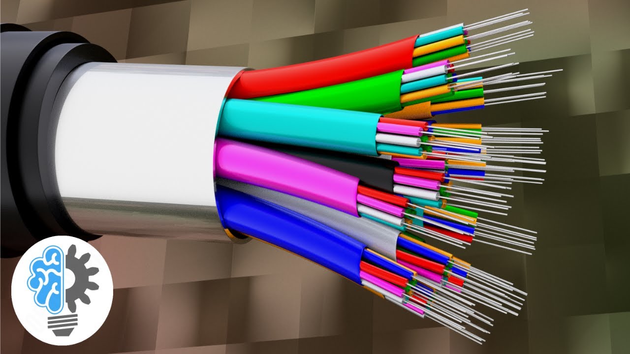
When two fibers are coupled, a key requirement is to ensure that light passes from one fiber to the other without excessive loss or back reflection. What continues to be a challenge is keeping the finish pristine. A single particle coupled to the core of a fiber can cause significant insertion loss, back reflection, and even equipment damage. Conducting a proactive fiber inspection is essential to ensure reliable fiber connections.
- Fiber End-Face Inspection
- Fiber Optic Continuity Test
When testing Fiber optic cable networks, a visible laser source connected to one end of the cable can be used to verify transmission to the opposite end. This type of optical fiber test has the sole mission of detecting serious defects in the fiber, such as macro bends. Fiber optic continuity tests can also be used to determine if the correct fiber optic cable has been connected to the correct position in the patch panel.
A Fiber Optic Identifier (FI) is a handy,
Handheld fiber optic test tool that allows you to identify and detect external optical signals at any point in the fiber link. Fiber optic identifiers can be used to confirm the presence of traffic on a fiber as well as the direction of transmission.
A visual fault locator (VFL) uses visible spectrum laser light to check fiber continuity as well as detect faulty conditions. The red light source will be visible through the coating at the point where a cable may break or have bad splices. For fiber optic runs longer than 5 km or where access to view the fiber is limited, an OTDR can be used as a fiber optic cable tester to identify any continuity issues.
Optical loss measurement
As the light source travels down the fiber, its power level decreases. The decrease in power level, which is also known as optical loss, is expressed in decibels (dB).
Some may wonder what the correct method for testing fiber optics is. The most accurate way to measure overall optical loss with fiber testers is to inject a known level of light into one end and measure the light level at the other end with an OLTS. Since the optical light source and power meter are connected at opposite ends of the link, access to both ends of the fiber is required to apply this method.
Optical power measurement
A power measurement is a test of the transmitter signal strength once the system in question is active. An optical power meter indicates the received optical power at your photodiode. In addition, it can be connected directly to the output of the optical transmitter or to a fiber optic cable at the point where the optical receiver would be located. Optical power can be measured in “dBm” units, where “m” represents 1 mill watt and “dB” refers to decibels.
Future of fiber optic testing
The potential of fiber optics as a means of communication seems limitless, thanks to new advances and possibilities that are continually being identified. Promising research on technologies such as “braided light” transmission could ultimately lead to a bandwidth improvement of the order of 100X on the same single-mode fiber.


